Note
Go to the end to download the full example code.
Geometry
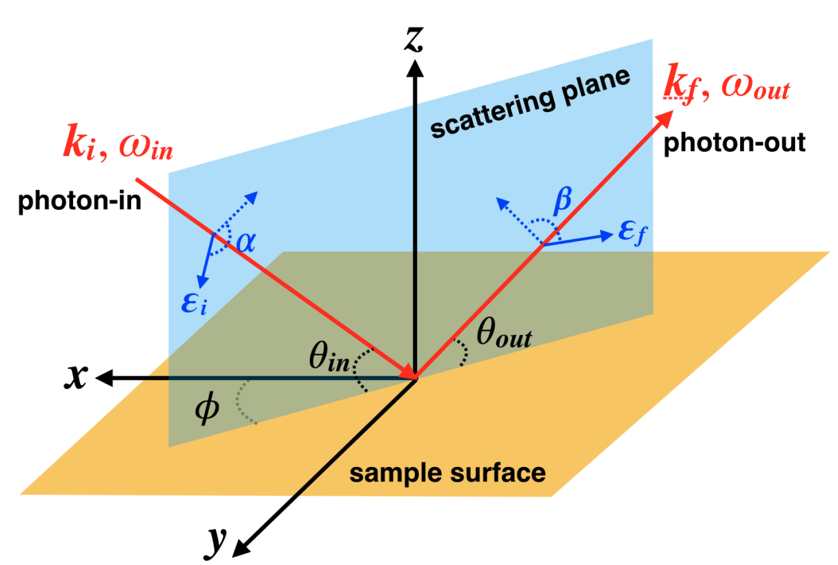
Here, we explain in more detail how geometry works in EDRIXS. From a physics point of view, the only requirement is that the coordinate system describing the crystal field and hopping is the same as the one describing the X-ray absorption and emission operators. For this discussion, it is useful to illustrate the standard RIXS geometry.
RIXS function
We begin by preparing a basic function to compute RIXS for an atomic model. As inputs, we include:
v_cfmat: the matrix defining the crystal field.thin: incident x-ray anglethout: emitted x-ray angleloc_axis: the matrix specifying how the crystal field is defined or equivalently the orientation of the samplescatter_axis: the matrix specifying how the x-ray geometry is set up
import edrixs
import numpy as np
import matplotlib.pyplot as plt
import contextlib
import io


def make_rixs(v_cfmat, thin, thout, loc_axis=None, scatter_axis=None):
    v_noccu = 8
    gs_list = [0, 1, 2]
    ominc = np.array([853])
    gamma_f = 0.1
    pol_type = [('linear', 0, 'linear', 0), ('linear', 0, 'linear', np.pi/2)]
    info = edrixs.utils.get_atom_data('Ni', '3d', v_noccu, edge='L3')
    slater = [[s[1] for s in info['slater_i']],
              [s[1] for s in info['slater_n']]]
    off = 871
    with contextlib.redirect_stdout(io.StringIO()):
        out = edrixs.ed_1v1c_py(('d', 'p32'), shell_level=(0, -off),
                                v_cfmat=v_cfmat, loc_axis=loc_axis,
                                c_soc=info['c_soc'], v_noccu=v_noccu, slater=slater)
    eval_i, eval_n, trans_op = out

    eloss = np.arange(-1, 5, 0.01)
    with contextlib.redirect_stdout(io.StringIO()):
        rixs_all = edrixs.rixs_1v1c_py(
            eval_i, eval_n, trans_op, ominc, eloss,
            gamma_c=info['gamma_c'], gamma_f=gamma_f,
            thin=thin, thout=thout, scatter_axis=scatter_axis,
            pol_type=pol_type, gs_list=gs_list)

    rixs = rixs_all.sum(axis=(0, 2))
    return eloss, rixs
Crystal field in a non-standard geometry
For an example, let’s consider a \(d\)-electron material with a tetragonal crystal field using \(L\)-edge RIXS. The standard EDRIXS function for a tetragonal crystal field will use \(z\) as the four-fold symmetry axis.
v_cfmat = edrixs.cf_tetragonal_d(2.09, 0.15, 0.08)
How can we deal with a case where the sample surface is, in fact, not parallel
to the crystal field \(z\)-axis?
Instead the \(z\)-axis is parallel to the sample surface
within the scattering plane and the sample surface normal is the
\(x\)-axis. We have also defined our incoming and outgoing x-ray angles
thin and thout with respect to the sample surface.
thin = np.deg2rad(30)
thout = np.deg2rad(120)
There are several options to describe this situation:
Re-define angles
A simple approach to the problem is to alter the angles so they are correct with respect to the orientation of the crystal field matrix.
angle_offset = np.deg2rad(90)
eloss, rixs0 = make_rixs(v_cfmat, thin-angle_offset, thout+angle_offset)
Set crystal field axes
The loc_axis variable allows you to tell EDRIXS the axes used to set
up the crystal field. It will then transform the axes used to compute the
x-ray absorption and emission operators. The columns of loc_axis
should denote the axes used for the crystal field in the \(x\),
\(y\), \(z\) frame used for the absorption operators. We include a
consistency check between this matrix and what is expected from the
angle_offset variable.
Set geometry axes
The scatter_axis variable makes EDRIXS rotate the absorption and
emission operations. The columns of this matrix should express the local
scattering axes in the same global \(x\), \(y\), \(z\)
coordinates used for the transition operators.
scatter_axis = loc_axis
eloss, rixs2 = make_rixs(v_cfmat, thin, thout, scatter_axis=scatter_axis)
Redefine crystal field
Although a little more complicated, it can be helpful to redefine the crystal field in some cases. This can be done using a Wigner d-matrix in terms of angular rotations around the axes. The spin also needs to be rotated by a spinor matrix. In this case, we need to rotate 90 degrees around the \(y\)-axis.
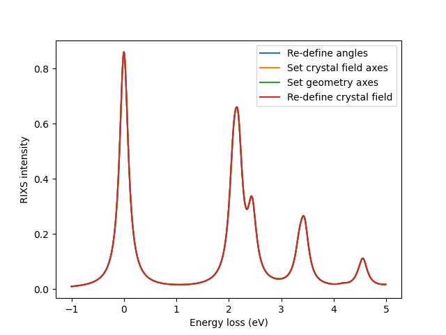
Check consistency
Let’s show that all these methods are consistent.
np.testing.assert_allclose(rixs0, rixs1)
np.testing.assert_allclose(rixs0, rixs2)
np.testing.assert_allclose(rixs0, rixs3)

fig, ax = plt.subplots()
ax.plot(eloss, rixs0, label='Re-define angles')
ax.plot(eloss, rixs1, label='Set crystal field axes')
ax.plot(eloss, rixs2, label='Set geometry axes')
ax.plot(eloss, rixs3, label='Re-define crystal field')
ax.set_xlabel('Energy loss (eV)')
ax.set_ylabel('RIXS intensity')
ax.legend()
plt.show()
Total running time of the script: (0 minutes 1.267 seconds)